New

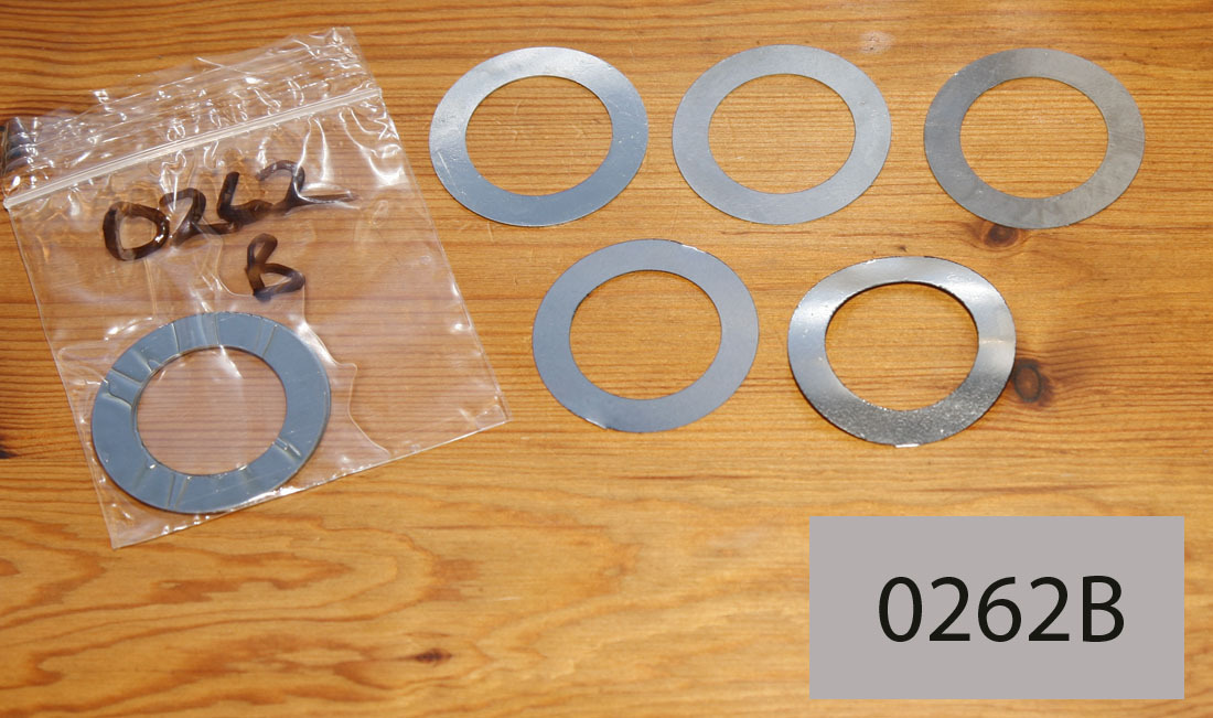
SOHC All Models - Mainshaft Drive Side Shim - Set of 4 Shims In Various Thicknesses

Product no.: 0262b A11/46a-s

In stock

£16.00

Recommended Retail Price, plus delivery


Fitted to the Drive Side Mainshaft (inside the crankcase) and essential when rebuilding your engine to ensure that the crankshaft and conrod are positioned correctly in relation to the barrel - these Drive Side Crankcase Shims are to fit all SOHC (and most later DOHC engines) - i.e. CS1, Model 30/40 (Internatioal), 30M/40M and Manx models. 

This Item listing is for a set of 4 shims - one of each in the thicknesses shown below (and slightly cheaper than if buying individually - but you may find you want more of one particular thickness, so we also sell individually).

Note: we also sell these shims individually - which is Item 0262 next to this listing in the same section.

Shims are available in the following thickness:

- 0.1mm = 0.004" or 4 thou

- 0.2mm = 0.008" or 8 thou

- 0.3mm = 0,012" or 12 thou

- 0.5mm = 0.021" or 21 thou

It is common practice to keep a number of these shims available when rebuilding your engine, and assembling the bottom end.  It is worth noting that for the SOHC and DOHC Norton engine design - the crankshaft is positively located to the Timing Side Main bearing (i.e. it is locked in place to this bearing - the drive side mainshaft and its bearings are effectively 'floating', so normally shimmed after the timing side shimming is complete.


Shimming the crank in the crankcases on a SOHC (and most DOHC) Engine: Background Information and Helpful Hints:

The process of shimming a SOHC (or DOHC) is particularly important, as the safe and efficient running of the bevel gears are dependant on this being done correctly.

However, before starting the process of shimming the bevel gears (to the correct mesh and backlash) - it is necessary to shim the crankshaft within the crankcases.

The key objective of this process is to ensure that the conrod (and Big End bearing) are correctly centered in the crankcase - so that the piston (and Little End) has no unwanted side thrust applied against them - because the conrod is off centre.

This is a relatively simple process, but the important thing to remember is - the crank is 'locked' to the Timing side crankcase (i.e. it is the process of assembling the crankshaft bevel gears, oil pump drive gear and finally the timing side LH mainshaft nut, that finally locks the crankshaft to the Timing Side Main bearing.

Once having correctly centralised the crankshaft, by using the shims shown here - either one or multiples shims being used to achieve this - and having temporarily locked up the LH crankshaft nut with gears in place - ensure that the conrod is sitting central to the centre line of the two crankcase halfs.

Note: Norton roller Bigends always have a small amount of sideplay, i.e. the conrod can move sideways on the rollers, between the two flywheels a small amount - so you need to take this into account when ensuring the crank is centralised.  A few ways to do this (i.e. hold the conrod up against one sidewall, then measure the total offset using a digital clock or similar, for it to move to the opposite wall - then half this to find the central position, or similar) - but obviously, once done, it is relatively simple to move the conrod in the crankcases from side to side, and confirm when centralised, the conrod centrline is in line with the crankcases gasket face.

Then finally, once the timing side is shimmed correctly - you can shim the Drive Side Mainshaft (using shims with our Item Number 0262).  The purpose of shimming the drive side mainshaft is to prevent excess 'float' of the drivside roller bearing inner race along the driveside mainshaft.  It is difficult to find much information in Norton literature on what is considered the normal acceptable 'End Float' of the innermost driveside roller bearing  - but I normally look for at least 10 - 15 thou when the engine is cold (i.e. how much the inner driveside roller race can move back and forth along the mainshaft before coming into contact with the flywheel wall or the inner crankshaft spacer fitted between the driveside inner roller and the outer driveside ball bearing (remembering a roller bearing should always be fitted innermost to the flywheels, with a ball race outermost, closest to the engine sprocket).

It should be remembered that original fitment of the roller bearing was a 'lipped bearing' - and if this is fitted, then the shimming on the drive side crank should ensure the rollers are not being pushed into the lip, once the crankcases are fully tightened up - again various ways of doing this, but firm grease, engineers blue or similar smeared on the outer race and roller lip is a good way of visually checking on trial assembly. 

It is not uncommon for unlipped roller bearings to be fitted as well (as good quality lipped roller bearings of this size are now obsolete and very difficult to find) - and this should not be a problem - but important to bear in mind, this puts more emphasis on ensuring that the inner mainshaft spacer between inner roller race and ball race is of the correct thickness - and ensure that the rollers of the roller bearing are making full contact with the roller outer race once assembled.  Again - allowing for a small amount of end float. 


Therefore, the general order I apply when shimming the SOHC crankshaft in the crankcases is: 

1. Trial assembly of crank in the crankcases, with no shims at all fitted first.  Fit all crankcase bolts you have available and fully tighten. Once fully tightened, the crank should spin freely with no tight spots etc.  If the crank spins freely up until the final last half turn of the spanners - but then tightens up - that is a bit of a problem!!  It needs to be investgated - but it could mean you have negative clearance/endfloat on the crank.  This normally means something has gone amiss on assembly of main bearings or crank (or if building an engine up from spares and maybe wrong driveside spacers fitted.  But needs to be resolved before continuing -  crank must spin freely with no shims fitted, before continuing

2. Hopefully at the stage, it is is spinning freely - and you can move the crank backwards and forwards a small amount along the axis lines of the mainshafts - i.e. positive End Float

3. To measure the amount of end float, one reasonable way to do this is place the crankcases bevel chamber face down (carefully!) on a wooden block or surface plate.  Then fit the engine sprocket in place temporarily (finger tight nut should be enough).  Then a dial gauge on some kind of stand firmly attached to crankcases (or surface plate) can be used, with dial pointer touching the side wall of engine sprocket (placed vertically above) - and the crank carefully lifted up and down by the sprocket, to measure endfloat

4. At the same time - you should also check where the conrod sits in relation to the crankcase centrelines (taking into account any conrod sideplay, as described earlier) - which should give a good indication of what thickness of Timing Side Mainshaft shims are required - Our listing 0263 for Alloy Inter/CS1 crankcases, or 0265 for Magnesium M30/M40/Manx crankcases

5. You can then split the crankcases and make up the correct thickness of shims (i.e. one or multiple shims) between the timing side main bearing and flywheel shoulder.  Reassemble and repeat process (one or multiple times!) until correct centreline alignment is achieved.  To do this you will need to trial fit the bevel gears and oil pump drive gear, in the bevel chamber, so the timing side LH thread crankshaft nut can be used to 'lock' the crank to the timing side main bearing.  This ensures correct measurement of the centralised conrod is achieved accurately.  This should result in an accurately positioned and centralised conrod/crank.

6.  Then finally, you can move to the Driveside mainshaft, and check the inner roller bearing race remaining endfloat - and shim this to ensure the roller inner race does not have excessive 'float' along the mainshaft (and in the case of lipped roller bearings - the rollers have a small amount of float until they touch the lip of outer race lip).  Hard to say exactly how much endfloat of the inner roller race is considered best - but I normally aim for at least 10 - 15 thou.

And of course - don’t be too surprised if you find this a long and somewhat fiddly process, we all do!, but at the end of it, you will be in a good position to carry  on assembly - and particularly, then move to the next task in assembly of the bottom end - the lower bevel gear shimming.

The information above is for assistance only - and of course all responsibility for assembly lies entirely with the customer, but we hope it helps.  We repeat this information in the item listings for all the SOHC crankcase shims


Customers who bought this product also bought

*
Recommended Retail Price, plus delivery

Browse these categories as well: 1.j Norton Gaskets/Seals for SOHC, OHV, SV Models, 1.e Norton SOHC Crankshaft Parts